


Crusher Machine for Clay Brick 2D Drawings and Design
A crusher machine for clay brick production is a vital piece of equipment used in the brick manufacturing industry. This article explores the functional aspects, design requirements, and the significance of creating precise 2D drawings for such machinery.
Introduction
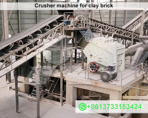
In clay brick production, the raw material must be prepared and shaped to achieve uniformity in size, texture, and composition. A crusher machine helps in breaking down large clay lumps into finer particles, ensuring the clay is ready for further processing. Creating accurate 2D drawings of these machines is essential for effective design, manufacturing, and maintenance.
Key Components of a Crusher Machine
A clay brick crusher machine typically includes the following components:
- Hopper: A funnel-like structure that feeds raw clay into the crusher.
- Rotating Blades or Rollers: Designed to crush and grind the clay lumps into finer particles.
- Motor and Drive System: Powers the crusher’s blades or rollers.
- Screening Mechanism: Separates crushed clay into desired particle sizes.
- Output Chute: Delivers processed clay to the next stage of production.
Design and 2D Drawing Essentials
2D drawings form the foundation for manufacturing a clay brick crusher machine. These drawings ensure precision and provide clear guidelines for engineers and technicians during production and assembly. Below are the key considerations when creating 2D drawings:
1. Dimensions and Scale
- Accurate dimensions of each component, such as the hopper, blades, and motor housing, should be clearly indicated.
- Use a standard scale (e.g., 1:10 or 1:20) to represent the machine’s overall size.
2. Material Specifications
- Specify the materials used for each part, such as steel for the blades or rollers and reinforced metal for the frame.
3. Assembly Views
- Include exploded views to illustrate how the parts fit together.
- Annotate fasteners, joints, and other assembly details.
4. Motion and Power Transmission
- Show the positioning of the motor and the connection to the rollers or blades via gears or belts.
- Highlight the direction of motion and force application.
5. Safety Features
- Depict protective covers over moving parts.
- Include emergency stop mechanisms and ergonomic controls.
Software for 2D Drawings
Several CAD (Computer-Aided Design) tools are available to create 2D drawings of crusher machines. Popular options include:
- AutoCAD: A versatile tool for detailed 2D and 3D mechanical designs.
- SolidWorks (2D Mode): Ideal for creating intricate machine part diagrams.
- SketchUp: Useful for conceptual designs and simpler layouts.
Advantages of Detailed 2D Drawings
- Improved Accuracy: Ensures that all components fit perfectly during assembly.
- Streamlined Production: Acts as a blueprint for manufacturing and reduces errors.
- Maintenance Guide: Serves as a reference for future repairs and upgrades.
Conclusion
The design and implementation of a clay brick crusher machine are integral to efficient brick manufacturing. By creating precise 2D drawings, engineers can ensure the machine operates effectively, meets production requirements, and adheres to safety standards. Leveraging advanced CAD tools further simplifies the design process, making it possible to develop optimized machinery tailored to specific production needs.
For those in the clay brick industry, investing in high-quality crusher machines and accurate 2D drawings can lead to significant improvements in operational efficiency and product quality.

