


Quarry Crusher Machine Diagram Flow Charts & Plant Layouts
When you search for a quarry crusher machine diagram, you aren’t just looking for a simple drawing; you are looking for the blueprint of profitability. A well-designed crushing flow chart is the skeleton of your quarrying operation. It determines your efficiency, your downtime, and ultimately, your cost per ton.
At Liming Heavy Industry, we don’t just sell machines; we design integrated systems. Whether you are processing hard granite, basalt, or soft limestone, understanding the logic behind the machine diagram is crucial for success.
Decoding the Crushing Flow: How It Works
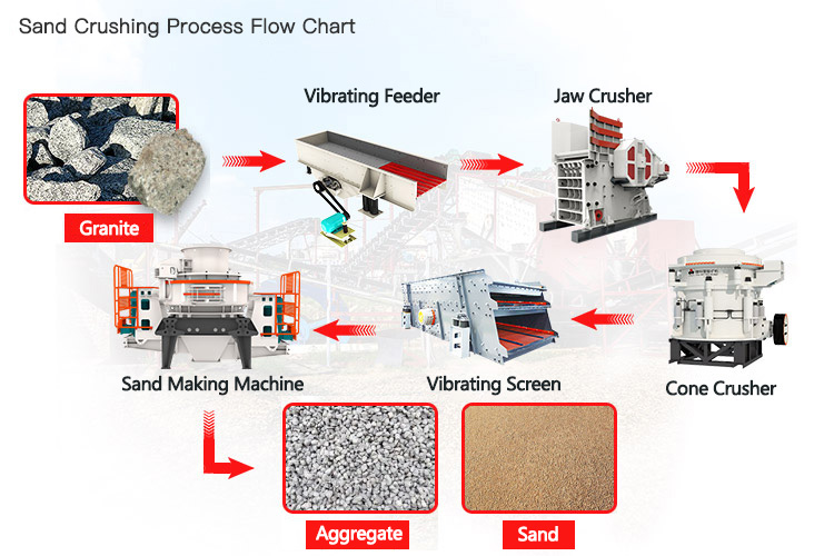
A standard quarry crusher machine diagram represents the lifecycle of a stone from the mine to the stockpile. While every site is unique, the core logic follows a proven multi-stage process to ensure optimal reduction ratios and particle shape.
1. Primary Crushing Stage
The raw material is fed via a Vibrating Feeder into the primary crusher. In most hard rock diagrams, the PE Series Jaw Crusher is the heart of this stage. It handles coarse materials and reduces them to a manageable size (usually 150-300mm).
2. Secondary & Tertiary Crushing Stage
The material is then conveyed to the secondary stage. For hard rocks, we utilize the HPT Hydraulic Cone Crusher; for softer rocks like limestone, an Impact Crusher is preferred. This stage dictates the final quality of your aggregates.
3. Screening & Recirculating (Closed Circuit)
This is the most critical part of the diagram. The Vibrating Screen separates the material. Stones that meet the size requirement are stockpiled, while oversized stones are returned to the secondary crusher. This “closed-circuit” design ensures precise product sizing.
Solving Your Core Pain Points Through Design
Many operators struggle because their plant layout was copied from a generic template rather than customized. Here is how Liming’s engineered diagrams address common industry pain points:
- Pain Point 1: Production Bottlenecks.
The Liming Solution: Our diagrams calculate the “throughput match” between the Jaw and Cone crushers. We ensure the secondary crusher has 15-20% more capacity than the primary output to prevent jamming and overflowing. - Pain Point 2: High Maintenance & Downtime.
The Liming Solution: We design spacious layouts. Our diagrams include designated maintenance platforms and hoist points, allowing for quick liner changes without dismantling the entire line. - Pain Point 3: Poor Particle Shape (Flakiness).
The Liming Solution: For high-spec aggregate requirements, our diagrams incorporate a VSI (Vertical Shaft Impact) shaper at the final stage, ensuring a cubic product that meets highway standards.
Social Proof: 200TPH Granite Crushing Project in Nigeria
To see a quarry crusher machine diagram come to life, let’s look at one of our successful installations.
Project Overview
- Location: Abuja, Nigeria
- Material: High-hardness Granite
- Capacity: 200-250 Tons Per Hour (TPH)
- Output Sizes: 0-5mm, 5-10mm, 10-20mm, 20-30mm
Core Configuration:
- Feeder: GZD1100x4200 Vibrating Feeder
- Primary: PE750x1060 Jaw Crusher
- Secondary: CS240 Symons Cone Crusher (Standard & Short Head)
- Screening: 2 sets of 4YZS1860 Vibrating Screens
Result: The client reported a 30% reduction in power consumption compared to their previous line due to the optimized flow design. The plant has been running stably for over 3 years.
From the Engineer’s Desk: Expert Advice
“Hello, I am Engineer Zhang, Senior Technical Director at Liming Heavy Industry with 20 years in the field.”
Here is my honest advice: Do not obsess over the crusher alone; obsess over the transfer points in your diagram. I have seen million-dollar plants fail because the conveyor angles were too steep or the surge hopper between the Primary and Secondary stages was too small.
Always include a buffer pile or a surge hopper in your diagram. It decouples the Jaw from the Cone crusher. If the Jaw stops for 10 minutes, your Cone can keep running from the buffer. This simple addition in the layout can increase your daily uptime by 15%.”
FAQ: Quarry Crusher Machine Diagrams
How do I choose between a stationary and a mobile crusher diagram?
If your mining site has a lifespan of over 5 years and requires high capacity (>300TPH), a stationary diagram is more cost-effective. If you have multiple small sites or limited electricity access, a mobile (K Series) station is better.
Can Liming provide a custom flow chart for my specific rock type?
Yes. We require your raw material hardness (Mohs), maximum feed size, and desired output capacity. Our engineers will generate a CAD flow chart and 3D simulation specifically for your site.
What is the difference between Open Circuit and Closed Circuit diagrams?
An Open Circuit allows material to pass through only once, which may result in oversized particles. A Closed Circuit (standard in Liming designs) uses a screen to return oversized material back to the crusher, guaranteeing product consistency.
Does the diagram include dust suppression systems?
Absolutely. Modern environmental standards require it. Our diagrams integrate spray pipes at discharge points and can include full dust collection units for dry processing plants.
Get Your Custom Plant Design Today
A diagram is the first step toward a profitable quarry. Don’t rely on guesswork. Let Liming Heavy Industry’s engineering team build a production line that maximizes your ROI.
Ready to start? Click the button below to share your requirements, and we will send you a customized technical proposal and quotation within 24 hours.

